Just a bunch of scattered Arduino notes.
Leonardo
-
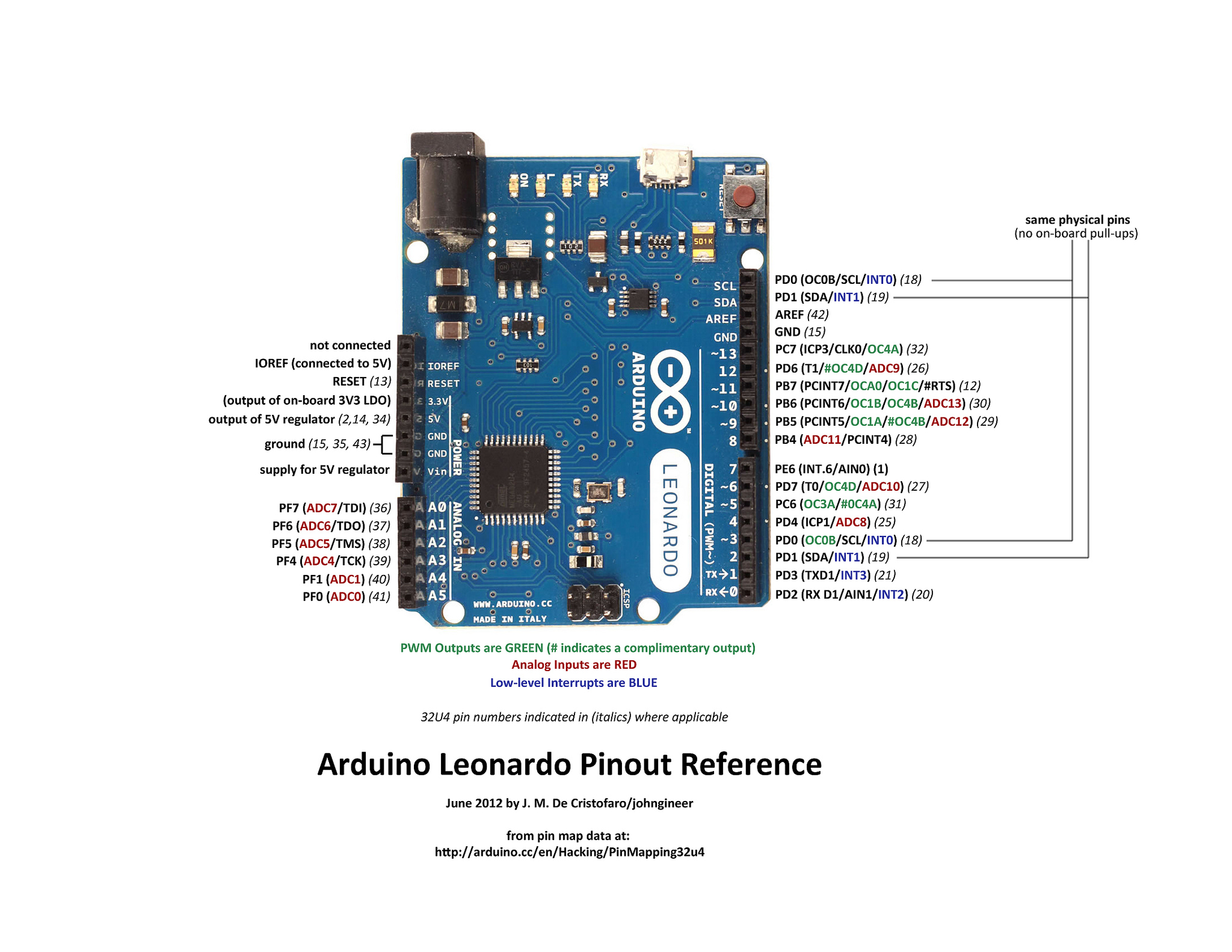
All data pins can be Digital Inputs or Outputs (i.e. D0-D13, A0-A5). Thus, 20 digital I/O pins
-
Caveat: D0 and D1 are shared by the UART bus used to communicate over USB. So if you want to avoid reading/writing weird values while connected to the PC, you may want to avoid these pins.
-
Pins D3, D5, D6, D9-D11, D13 have PWM’s attached to one of 3 (4) timers.
-
Timer1 (OC1x) on D9-D11 is the ‘fanciest’ timer. 😉
-
Pins A0-A5, as well as D4, D6, D8-10, D12 are all capable of Analog Input (not output)
-
To do analog out, use a PWM with some magic: https://arduino-info.wikispaces.com/Analog-Output
-
Each set of pins is a block. https://www.arduino.cc/en/Reference/PortManipulation
-
PORTD is D0-D7 (8 bits*, DDRD)
-
PORTB is D8-D13 (6 bits, DDRB)
-
PORTC is A0-A5 (6 bits, DDRC)
-
Set the DDRx registers directly to write bytes (i.e.
DDRD = B11111100;). You can read them too, and mask-out the data you’re not using -
B11001010 macros can be used for bitmasks, etc
-
PinMode(pin,mode) – mode can be INPUT, OUTPUT, or INPUT_PULLUP
-
INPUT_PULLUP not available on D0 and D1.
-
D0 and D1 are actually the same pins as SCL and SCA. On the board twice for some reason.
-
Standard 4 pins with support for interrupts D0-D3. Leonardo does actually have one more (D7)
-
Serial.print(), Serial.println() to output to the PC console over UART. https://www.arduino.cc/en/Reference/Serial
Protocols
UART
Has 1 channel. Not ‘true’ UART, as true UART runs at 12v.
- Uses Pins D0 and D1 (because of interrupts?). These pins also lack the optional pull-up resistors found on other Arduino pins.
- 3 actual wires: TX, RX, GND. TX=Transmit, RX=Receive. Typically White, Green, Black
- Data rate is typically 112 kHz (115200), but could be double that (230400)
- Is technically “Full Duplex” because of the separate Transmit and Receive lines
- Serial UART is an asynchronous protocol, WITHOUT a transmitted clock.
- Devices must agree upon the data rate ahead of time, and must run their own perfectly sync’d clocks.
- Primarily limited to communication between 2 devices. In theory multiple is possible, but it’s just not practical.
1-Wire
For that temperature sensor (DS18B20).
- Uses ??
http://playground.arduino.cc/Learning/OneWire
I2C/TWI (2-Wire)
For a variety of breakout chips. 16bit ADC (ADS1115), DAC (MCP4725), 64k EEPROM (24LC512), 128k SRAM (23LC1024*), 16bit Digital I/O Expander (MCP23017).
Loosely related to SMBus. Some SMBus devices could work over I2C.
- Uses D2 and D3 (because of interrupts)
- 3 actual pins: SCL, SDA, GND. SCL=Clock, SDA=Data
- Open Drain, using 3-state logic (high, low, high-impedance).
- Master/Slave(s). Technically it can have multiple masters, but the masters can’t directly talk to each-other over the bus (need to negotiate via another way).
- Either 112 (7 bit w/ reserved) or ~1000 (10 bit) devices can be on the bus. Each needs a unique (often hardwired) ID. Chips often have extra pins you ground to set the unique ID to 1-or-more values, but it means you still have a limit of 2-8 instances of the same device on a bus.
- Data rate is either 100 kHz, or 400 kHz. Later specs allow 1 MHz, 3.4 MHz and 5 MHz, but we don’t get to use those.
- SCL and SDA have pull-up resistors, connected to the Master’s power. I.e. the default state is High.
- Slaves ground the data line, to make the low signals. To go high, you leave it open.
https://learn.sparkfun.com/tutorials/i2c
SPI (4-Wire)
For SD Cards, Flash Memory (W25Q80BV), 10bit ADC (MCP3008), …
- ???
https://learn.sparkfun.com/tutorials/serial-peripheral-interface-spi